Amperis Especialistas en equipos de medida y mantenimiento eléctrico.
Le ayudamos
El objetivo de Amperis es ofrecer una completa gama en equipos de medida eléctrica, instrumentación de mano y equipos de ensayo y diagnóstico de subestaciones, líneas y centros de transformación.
Nuestros ingenieros se esforzarán al máximo en entender sus necesidades y hábitos de trabajo para asesorarle en el equipo más adecuado.
Productos destacados

Sobre nosotros
Amplia gama de productos
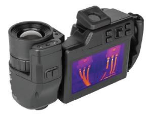
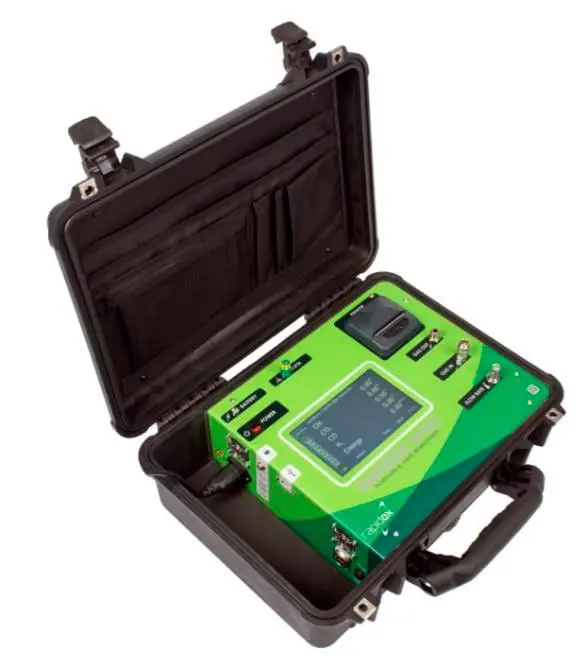
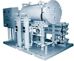
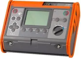
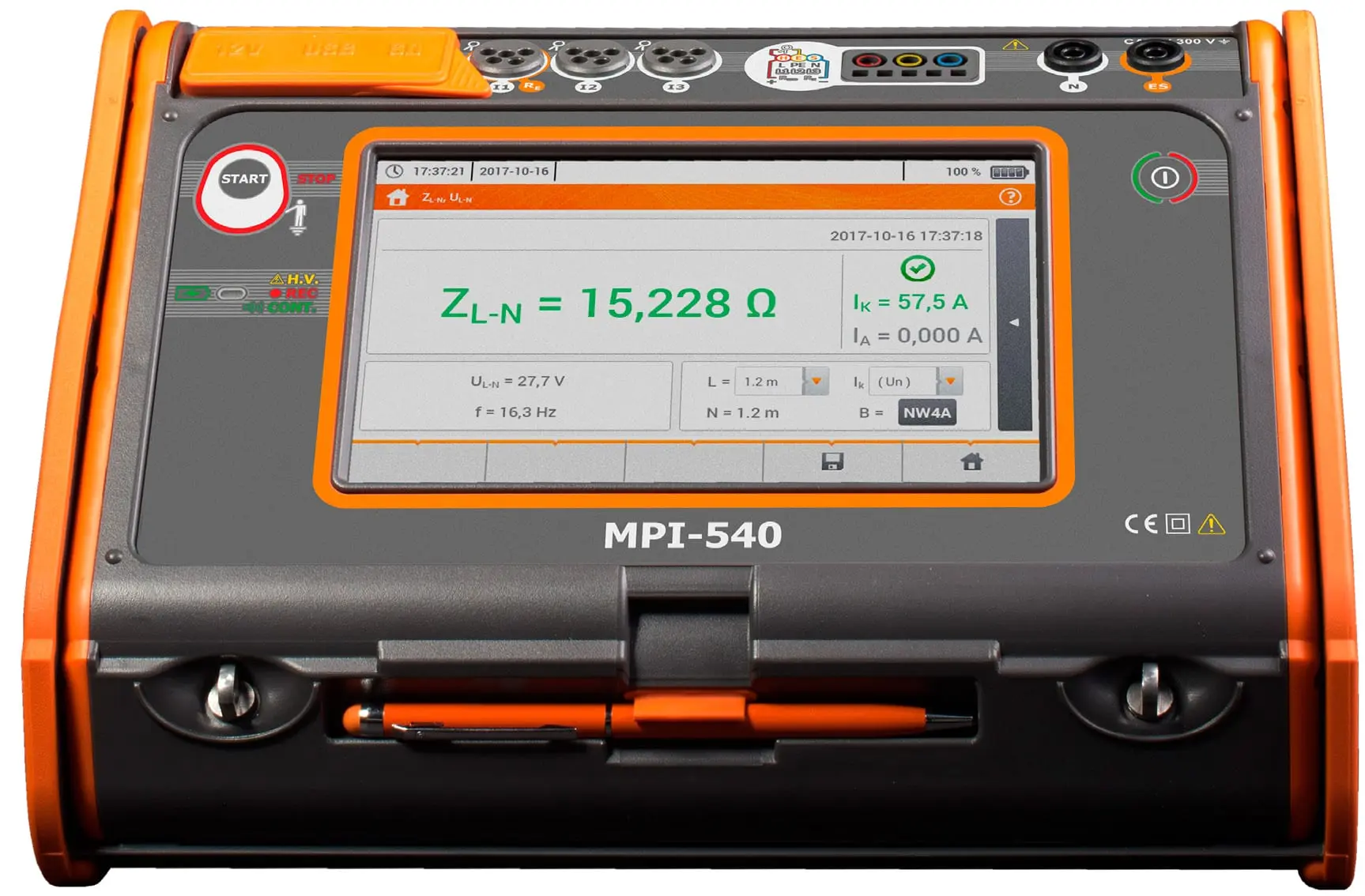
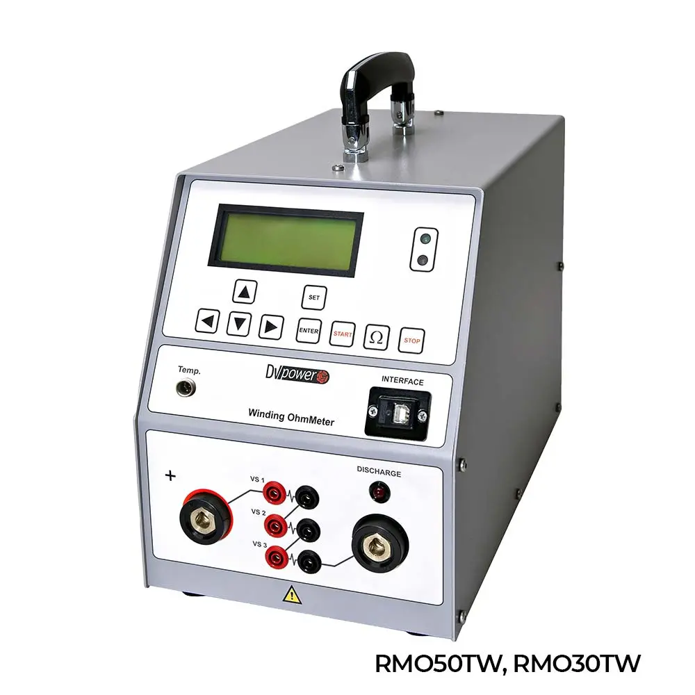
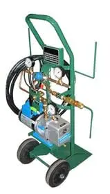
Disponemos de un amplio catálogo de productos, entre los que se encuentran ohmímetros, analizadores, cámaras termográficas, descargadores y cargadores de baterías, y un largo etcétera.
Certificado ISO-9001:2015
La calidad de nuestro trabajo ha sido auditada por SGS, lo que ha hecho que contemos con el Certificado ISO-9001:2015.
Asesoramiento personalizado
Nuestro equipo de ingenieros le asesorará en sus necesidades para ayudarle a elegir el mejor producto.
Especialistas
Nos dedicamos a la instrumentación de última tecnología para el diagnóstico y ensayo de subestaciones eléctricas, lo que hace que seamos especialistas en nuestro sector.
Multinacional
Nuestros equipos han sido vendidos en 58 países, lo que demuestra la calidad y fiabilidad de todo nuestro catálogo de productos.
Comprometidos con el medio ambiente
Para demostrar nuestro compromiso nos hemos registrado como productor de equipos electrónicos ante el Ministerio de Industria y se ha contratado a una fundación para el reciclaje de los equipos.