Battery discharger troubleshooting Guide
Components needed to run the test on Battery Discharger (BD):
- Voltmeter tester
- Battery (from 12V to the maximum possible for the BD)
Troubleshooting
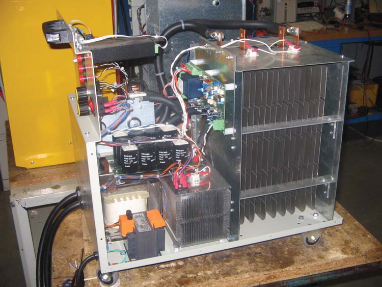
A) Remove the 2 side panels and the cover. Check that all the connectors and connection are properly connected.
B) Connect the BD to the power supply with the battery disconnected.
Turn on the main switch.
Check if the display lights.
Check if all the fans work and check the voltages on the Transformer (Picture 2).
INPUT: 0-230Vac or 0-115Vac
OUTPUT: 0-24Vac and 0-230=Vac
If some fans don't work, check if are correctly powered.
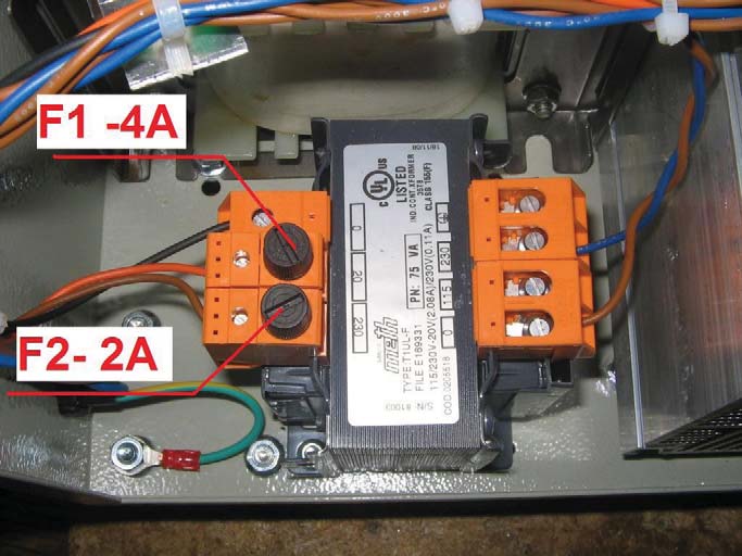
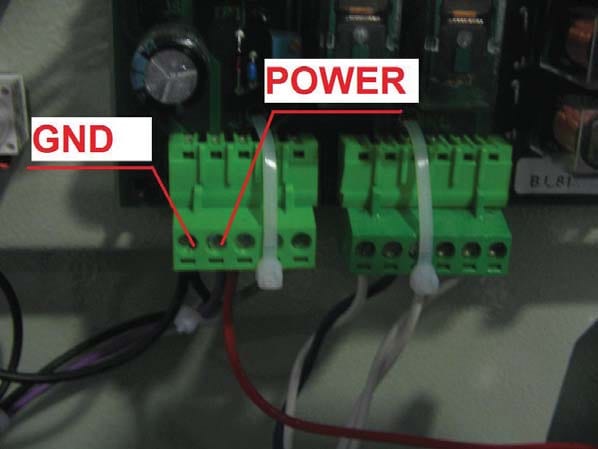
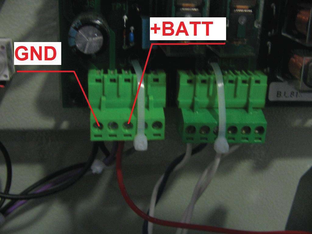
If the display board doesn't light check the input voltage on the board (Picture 3), and check the fuses on the transformer. The input POWER voltage on the digital board is 26-28Vdc (refer to GND as 0V). If the power is OK but the digital board doesn't light, replace the board.
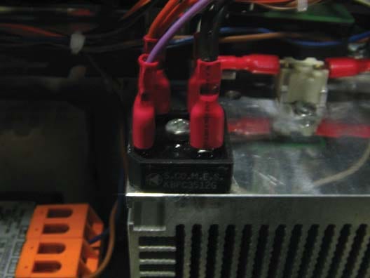
If the voltage on the trasformer is OK but the board isn't powered, check the rectifier (picture 4).
If the power supply is OK , the display shows voltage 0V/0,5V.
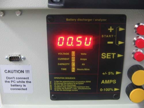
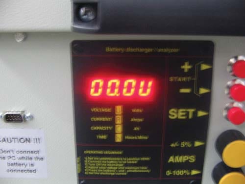
After few seconds the display shows the final discharge voltage (Picture 6).
E) Follow the same instruction in the manual for the begginning of a cycle of discharge.
- 1. Press SET to confirm the final discharge voltage (00.0V). The display shows the maximum time of discharge (10.0H).
- 2. Press SET to confirm. The dispay shows (RDY)
- 3. Press UP and DOWN together to begin the discharge cycle. If the main current potentiometer (POT1 – see the schematics) is in position 0 the display shows ( 0A ). If POT1 isn't in position 0 the display shows POT. Move POT1 in position 0.
- 4. Move the main potentiometer in a position different from 0.
The display shows the current 0A. If the display continue to shows POT, go to step G).
F) Check behind the display board if the 2 relays shown in the following picture are both closed.
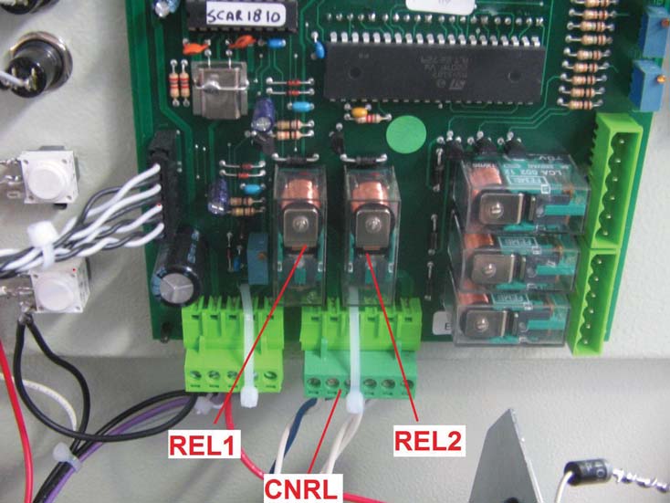
To perform the test, check the circuit continuity, with the tester, between the pins 1-3 and the pins 4-6 of CNRL connector (Picture 7). If the 2 relays are both closed ==> OK (go to item H else go to item G).
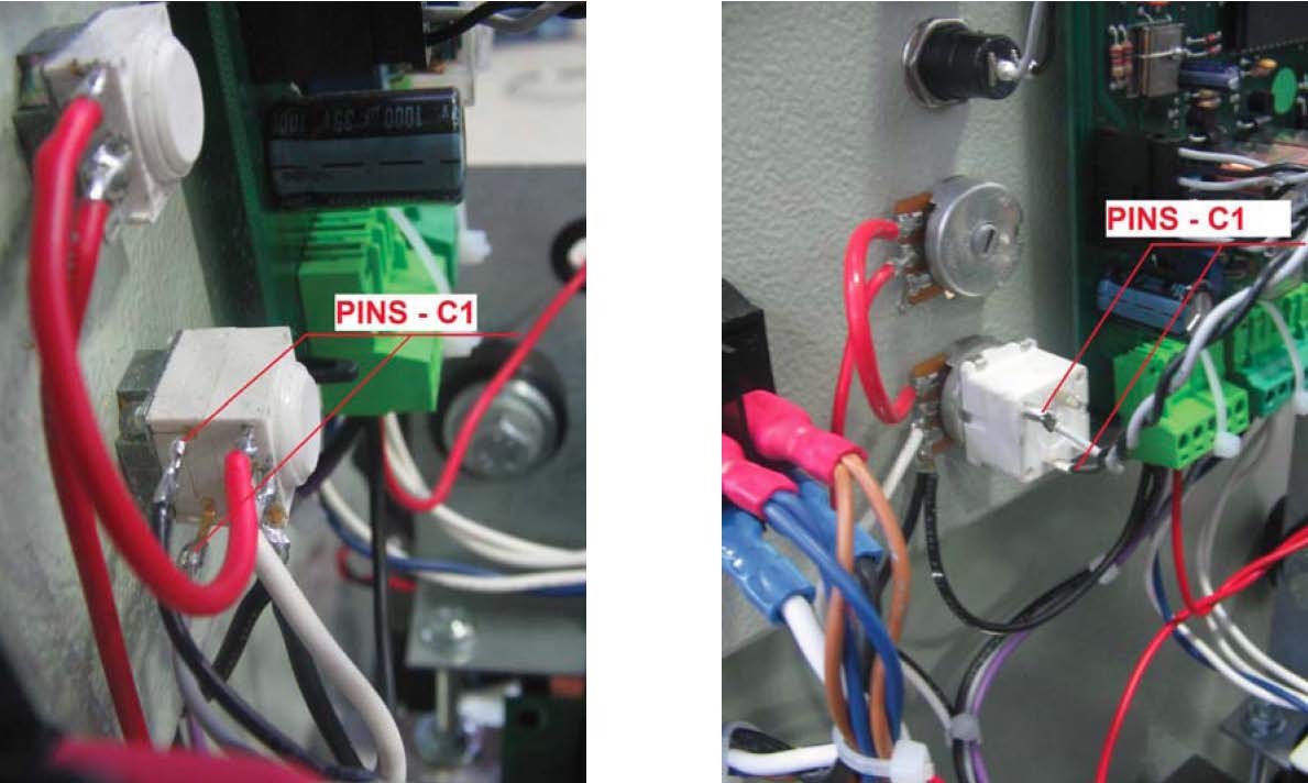
G) If the 2 relays are both opened check if the switch C1 (see the schematics) inside the main potentiometer, is closed. In the following pictures are shown the main potentiometers (old and new version) and the pins of the switch C1.
If there is continuity between the two pins of C1 but the two relais REL1 and REL2 aren't both closed replace the display board. If there isn't continuity between the two pins of C1, replace the main current potentiometer.
H) Check if the driver board is powered (see the following picture). Only the green led have to be ON. If Yes go to item I.
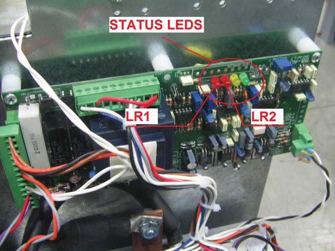
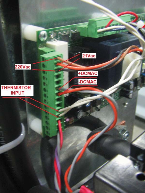
If the red led LR1 is ON check the continuity in the pins of the thermistor input (Picture 10).
If there isn't continuity, check again if REL2 of the control board is closed (item F) and check the continuity of the three thermistor ( 2 over the resistor pack and 1 near the IGBT module). Picture 11 and 12. Check also the wiring that connect toghether the thermistor with the two boards. Replace the thermistor if there isn't continuity circuit.
If the yellow led is ON and/or the red led LR2 in ON with battery not connected replace the driver board. If all the led are OFF check the power supply of the driver board (220Vac/21Vac – Picture 10) , check again if REL1 (Picture 7) of the display board is closed ad if the corresponding wiring are OK. If the power supply of the driver is not OK check again the output voltage of the Transformer, the fuses, and the wirings. If the power supply is OK but the driver is OFF, replace the driver board.
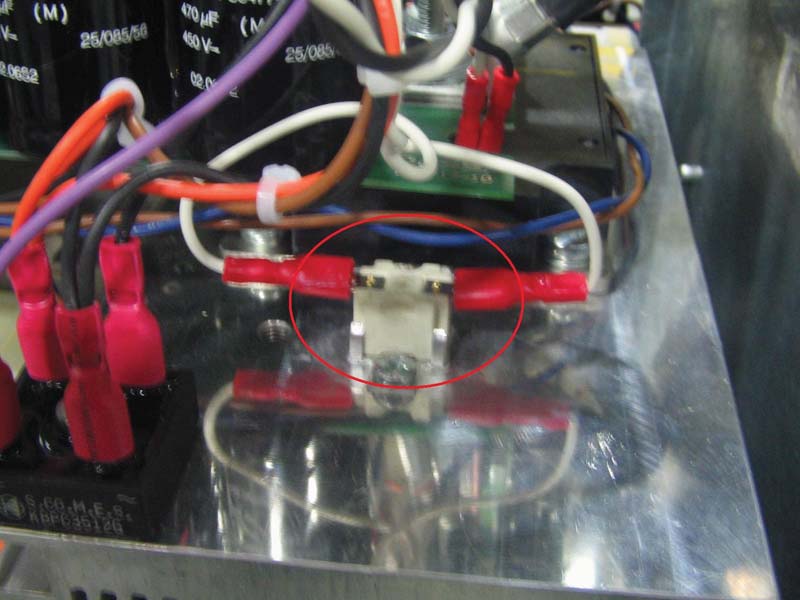
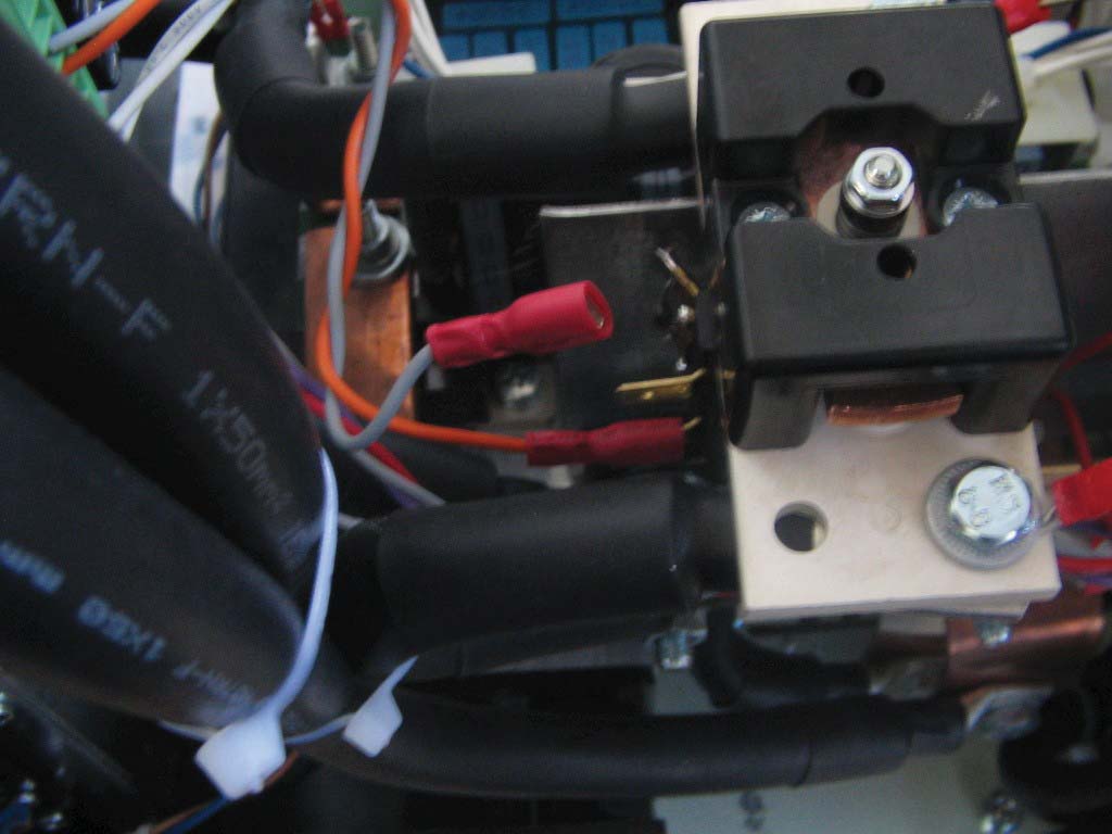
I) The driver is correctly powered. Check if the output contactor T0 is closed (Picture 13).
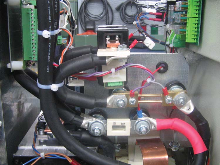
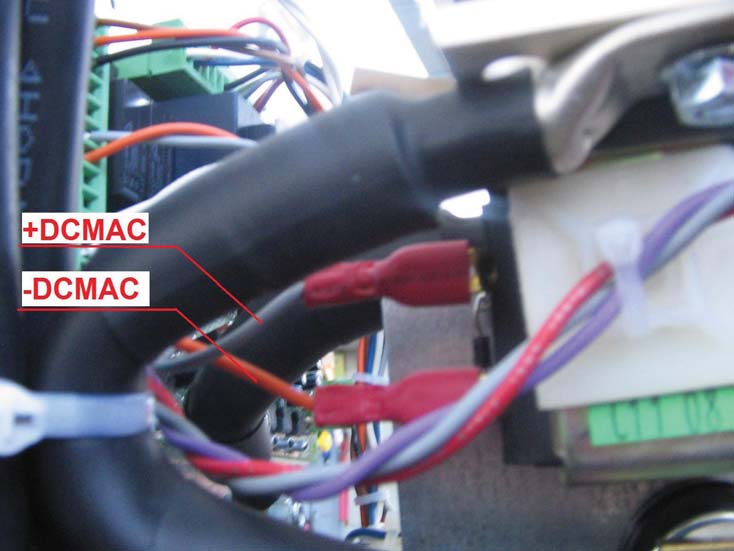
If it's opened check the contactor power supply (+DCMAC / -DCMAC on the driver) and the wiring (Picture 10 and 14). The power supply voltage on the contactor have to be 16-19Vdc. If the voltage is different, disconnect one of the connections +DCMAC or -DCMAC and test again the output +DCMAC/-DCMAC on the driver. (Picture 15). If the output voltage is OK change the contactor T0. If the output voltage is not OK change the driver board.
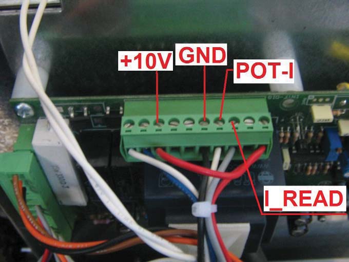
L) The driver board is ON ( only green led lights) and the contactor T0 is closed. Check the following voltage on the driver board. (Picture 16).
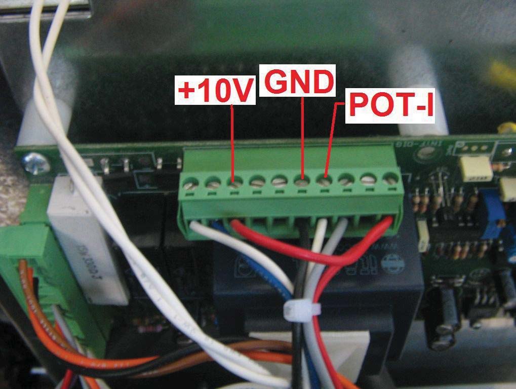
GND is the 0V reference. +10V have to be : 9-10V POT-I : moving the two current potentiometers from 0A to the maximum the voltage of this Pin move from 0V to 9/10V.
If +10V isn't OK, disconnect the two red wires from the connector shown in picture 16 and test again the voltage on +10V. If the value is OK the problem is on the current potentiometer so replace the two current potentiometers (the two current potentiometers will be supplied toghether as spare part).
If +10V isn't still OK replace the driver board.
If the voltage +10V is OK but the voltage on POT-I isn't OK replace the current potentiometers.
Check the following voltage on the driver board (Picture 17):
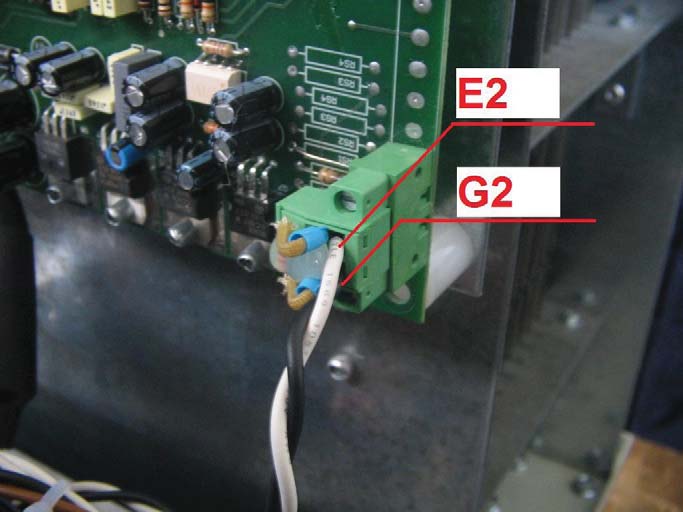
E2 is the 0V reference. The voltage on G2 have to be 13-15V. If the voltage isn't OK, disconnect the connector and test again the voltage on G2 (picture 18). The Battery have to be disconnected.
If the voltage is OK now, unmount the IGBT modue and test it using the 'TESTING IGBT MODULE' procedure. If the IGBT module is damaged, refering to the item Q, check the good condition of the resistor pack.
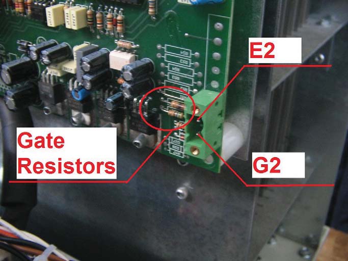
If the voltage is not OK and/or the gate resistor (Picture 18) seem burnt replace the driver and test the IGBT module following the procedure 'TESTING IGBT MODULE'. If the IGBT Module and the Driver Control baord are damaged the problem should be on the resistor pack. Refer to the item Q and check the good condition of the resistor pack.
M) If all the tests until now are OK, turn off the BD and connect the battery. Check if the capacitor bank (CAP) is correctly precharged (Picture 19).
The voltage have to be some volt less that the voltage of the battery. ( Voltage battery = 24V ==> the voltage on the Capacitor board have to be 22-23V).
The voltage will increase slowly until the battery voltage value.
If the voltage on the capacitors is not OK check the output fuse (FUSE) and the precharge circuit (R4 and D1). See the schematics. Replace if damaged. If all seem OK, but the volt on the capacitor board is 0V, disconnect immediately the battery and replace the capacitor board.
N) Turn on the main switch. Check if the digital board reads and shows correctly the battery voltage. If the battery voltage isn't OK check the battery voltage on the driver board (Picture 20), check the connection ( refer to the schematics ) and the connector.
If the battery voltage is OK on the digital board but the voltage shown isn't correct refer to 'the procedure to set the digital board'. If the problem isn't solved replace the display board.
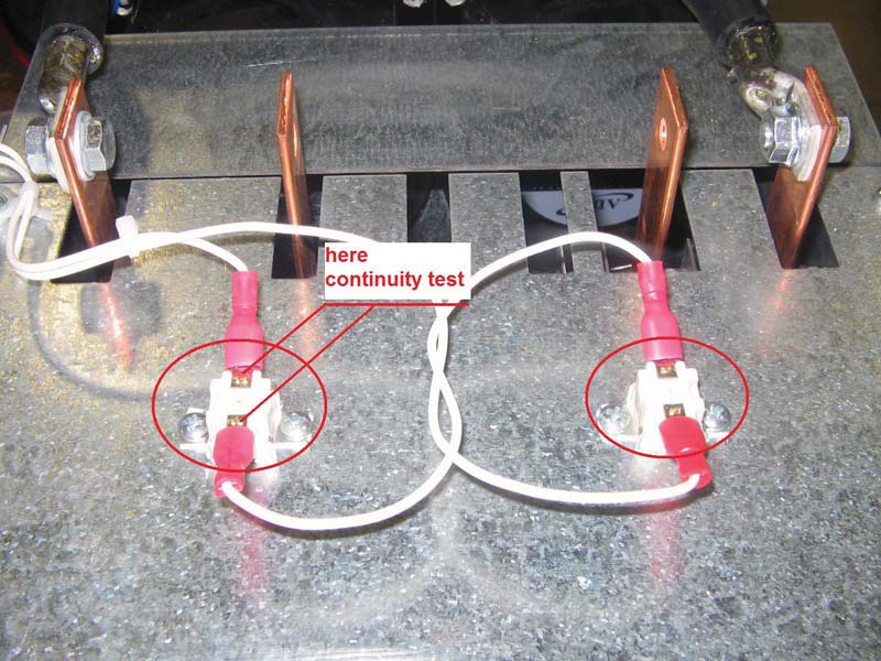
O) Check if the power contactor of T1 and T2 that manage the resistor bank are in the right configuration (Picture 21).
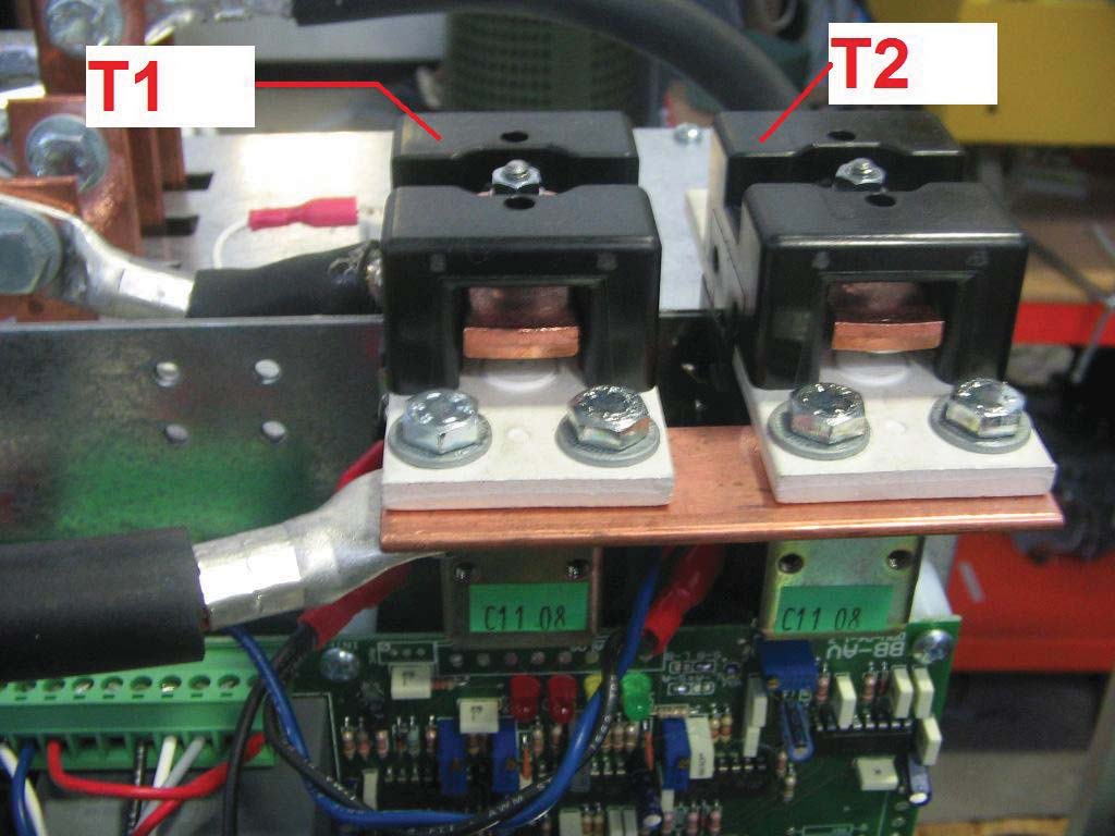
These are the configuration of T1 and T2 on the standard BD model 96V-200A 48V-200A. ( If you have a custom model or another type ask to Amperis Service).
| BD 96/200 | ||
| BATTERY VOLTAGE | T1 | T2 |
| V_BATT > 82V | OFF (OPENED) | OFF (OPENED) |
| 82V > V_BATT > 60V | OFF (OPENED | OFF (OPENED) |
| 60V > V_BATT >38V | ON(CLOSED) | OFF (OPENED) |
| 38V > V_BATT | ON(CLOSED) | ON(CLOSED) |
| BD 48/200 | ||
| BATTERY VOLTAGE | T1 | T2 |
| V_BATT > 38V | OFF (OPENED) | OFF (OPENED) |
| 38V > V_BATT > 28V | OFF (OPENED | ON(CLOSED) |
| 28V > V_BATT > 14V | ON(CLOSED) | OFF (OPENED) |
| 14V > V_BATT | ON(CLOSED | ON(CLOSED) |
If the configurations of T1 and T2 aren't OK, check if the contactors are correctly powered (follow the same step described on item I for T0). If the contactor are OK but the problem seem be on the digital board, refer to 'the procedure to set the digital board'.
If the problem is not solved replace the digital board.
P) Follow the same instructions in the manual for the begginning of a cycle of discharge (see also item E).
If all the items are been followed correctly and all seem OK the BD should work starting to discharge the current from the battery.
The current is controlled by the potentiometer. If the current is out of control and/or the fuse breaks, check again the items from H to M regarding the driver board, the IGBT module, the current potentiometer and, refering to item Q, check the resistor pack.
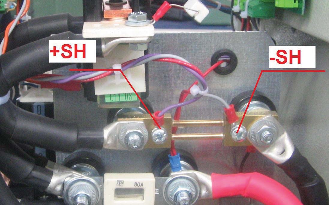
Check also if the shunt signal (+SH and -SH) are correctly connected to the driver board (picture 22).
If the BD are working but the display shows current equal to zero check the signal I_READ from the driver. (Picture 23 and Picture 24).
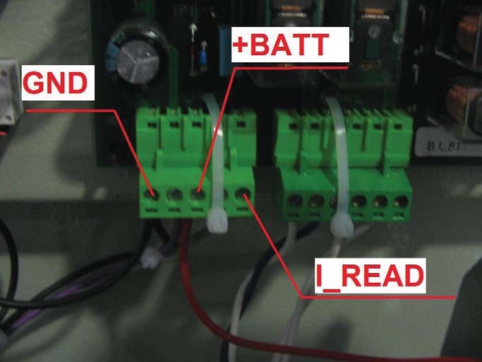
This signal have to be from 0V to 9/10V where 10V correspond to the maximum nominal output current (normally 200A). If the signal is OK but the display shows 0A or a wrong value, refer to the 'the procedure to set the digital board'. If the problem persists replace the digital board.
If the signal isn't OK, disconnect the connection of I_READ and test the signal on the driver (picture 23). If the signal isn't OK replace the driver.
If the problem regards the software of the digital board, for example:
fault on the couting time or counting Ah faulf on the setting off the maximum time or the minimum voltage of discharge refer to your Service Assistance.
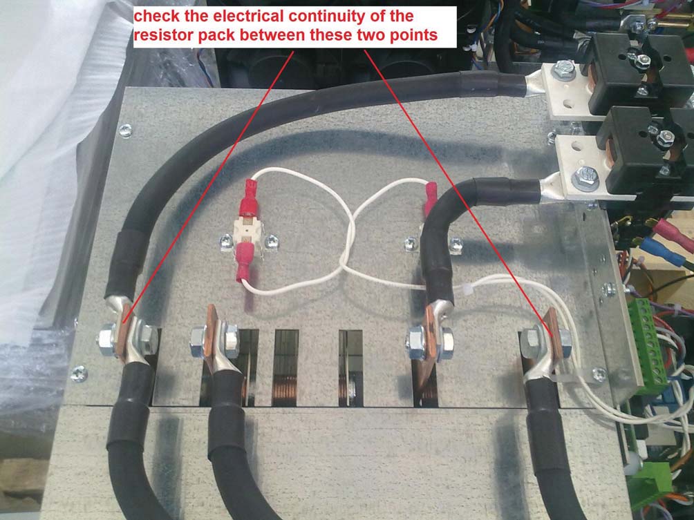
Q) Follow the same instructions on the manual for the begginning of a cycle of discharge (see also item E). If all, i.e. Contactors, Dispaly Board, Driver Doard seems to be OK, Potentiometers seem to be Ok but the discharge current is 0A, check the good status of the resistor pack.
In particular, with BD off, check with a tester the electrical continuty of the resistor pack. If its not present, the resistor pack need to be raplaced. If the resistor pack is damaged it's advisable to check also the IGBT Module that could be damaged to.
If you follow all these items and all seems OK, the BD should work. If you have some problems use this procedure to detect where should be the problem and send an e-mail to your Service Assistance.