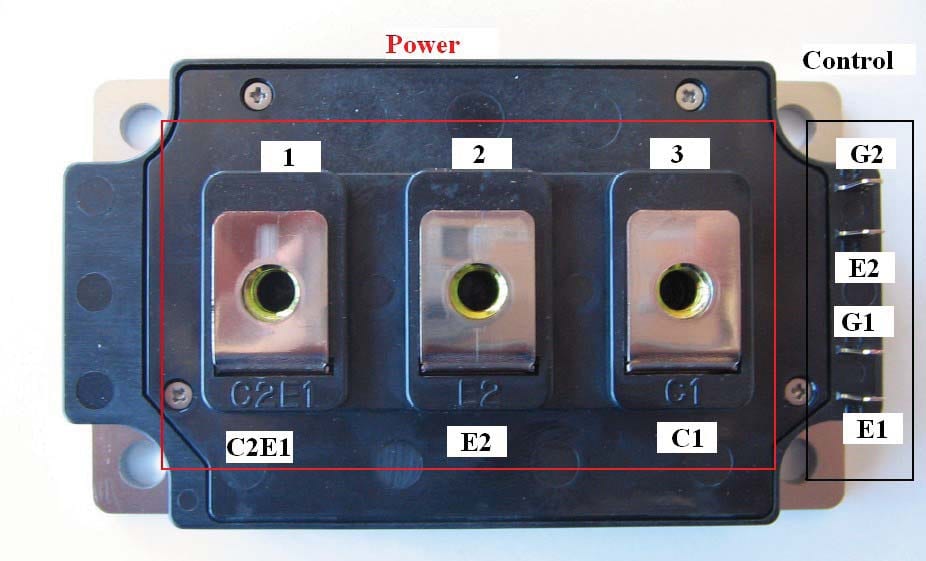
Testing dual IGBT modules of Amperis Battery Discharger
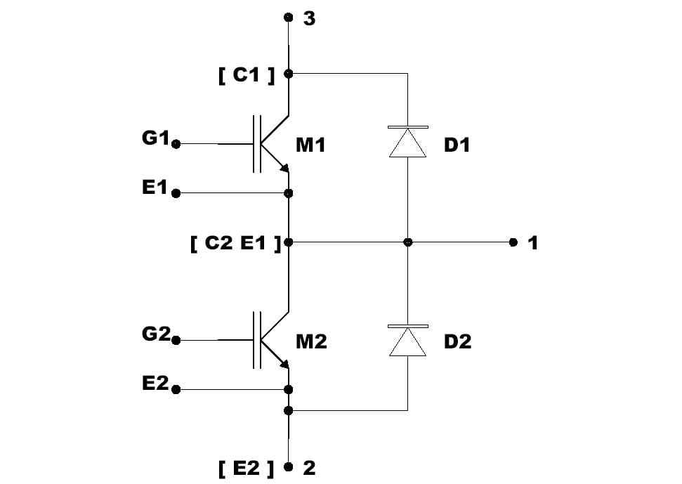
With ref to the electric schematic of Amperis Battery Discharger´s IGBT module, a dual IGBT module is composed by two Insulated Gate Bipolar Transistors (IGBT) with two Diodes in antiparallel.
IGBT modules can be tested rapidly, by using a standard multimeter, and the test consists in verifying three things:
- the Gate terminals are insulated from the relative Emitters;
- the Diodes are in good condition;
- the IGBTs are in good condition.
This type of IGBT testing procedure for Amperis Battery Discharger is not complete, because in order to verify the complete efficiency of these modules it's necessary to test them in real operating conditions.
However, this procedure is useful for a rapid pass-fail test.
WARNING!!!
IGBT Modules are very sensitive to ESD (Electro Static Discharge). It's recommended to handle them with care, to never touch the gate terminals and wear anti-static clothes.
WARNING!!!
Always use a battery powered multimeter to do this type of tests, with max battery voltage of 9VDC. If a voltage higher than 20VDC is applied between the gate terminals (G1-E1 G2-E2) the module will be damaged.
Test procedure
1) TEST OF THE GATES.
Set the multimeter in OHM measurement.
- ==> Verify that the control pins G1 and E1 are ISOLATED;
- ==> Verify that the control pins G2 and E2 are ISOLATED.
2) TEST OF THE POWER STAGE
Set the multimeter in DIODE testing mode.
- Connect together the pins G1-E1.
- Connect together the pins G2-E2.
Multimeter probes:
- 1) PROBE + ==> POSITIVE
- 2) PROBE - ==> NEGATIVE
A) Connect PROBE + of multimeter to terminal 1 of module and PROBE – to pin 3. The display of the multimeter should show the diode forward voltage (generally 0.6 - 0.8 V). If the display shows an open circuit or a short circuit the DIODE D1 is damaged.
B) Connect PROBE + of multimeter to terminal 3 of module and PROBE – to pin 1. The display of the multimeter should show an open circuit. If the display doesn't show an open circuit the IGBT M1 is damaged.
C) Connect PROBE + of multimeter to terminal 2 of module and PROBE – to pin 1. The display of the multimeter should show the diode forward voltage (generally 0.6 - 0.8 V). If the display shows an open circuit or a short circuit the DIODE D2 is damaged.
D) Connect PROBE + of multimeter to terminal 1 of module and PROBE – to pin 2. The display of the multimeter should show an open circuit. If the display doesn't show an open circuit the IGBT M2 is damaged.
- END OF TEST -